Design and size composite parts with the shopfloor in mind.
Virtua Composites CAE-CAM is manufacturing simulation software for engineers: sizing and toolpath planning that accounts for shopfloor constraints from the start, standalone or coupled with the CAD-CAE tools you already use.
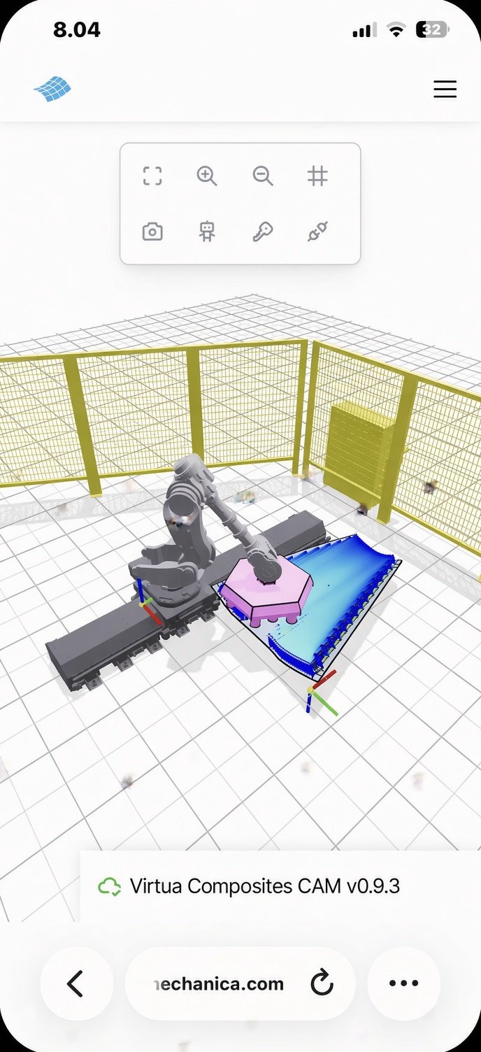
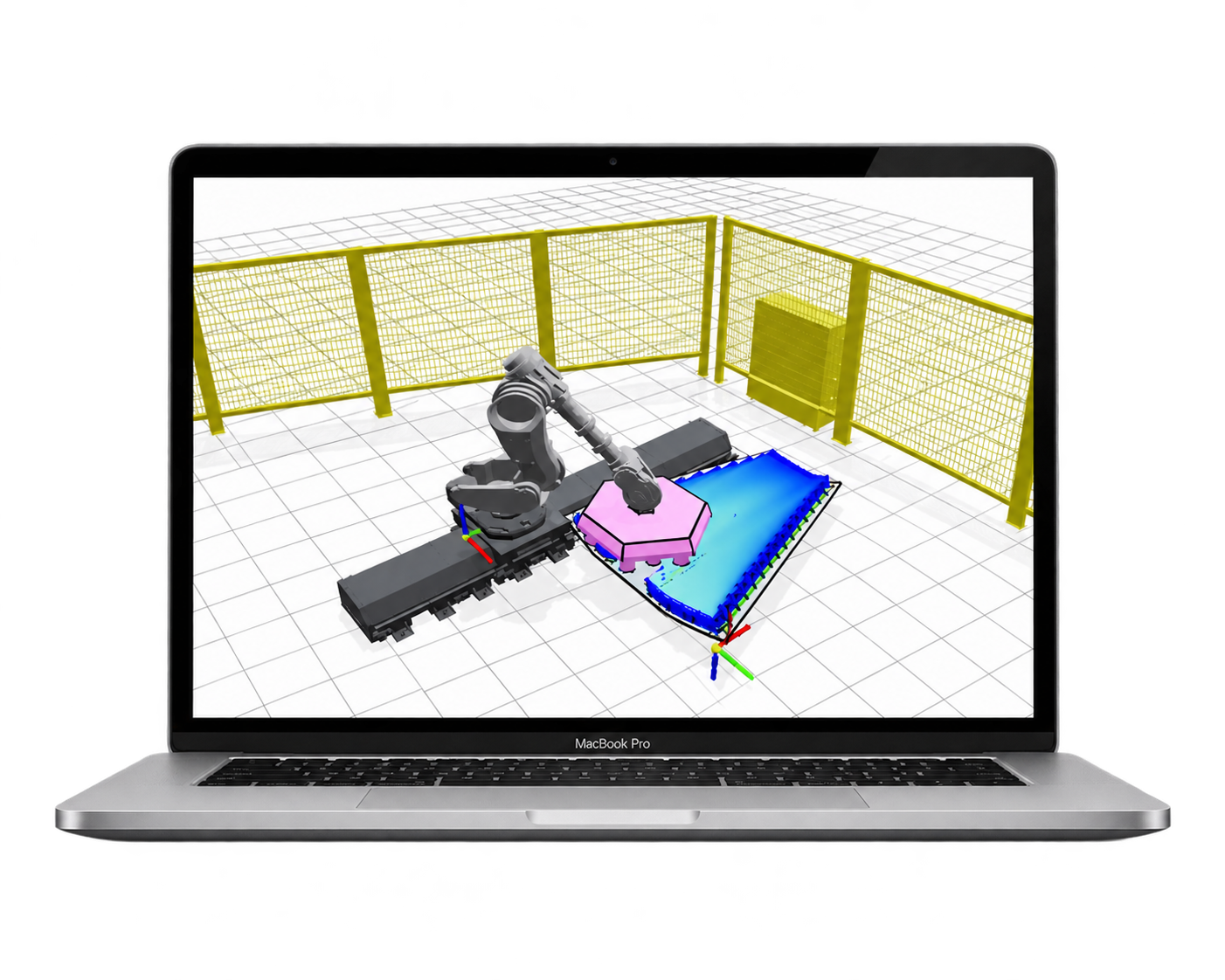
CAM application directly from your browser.
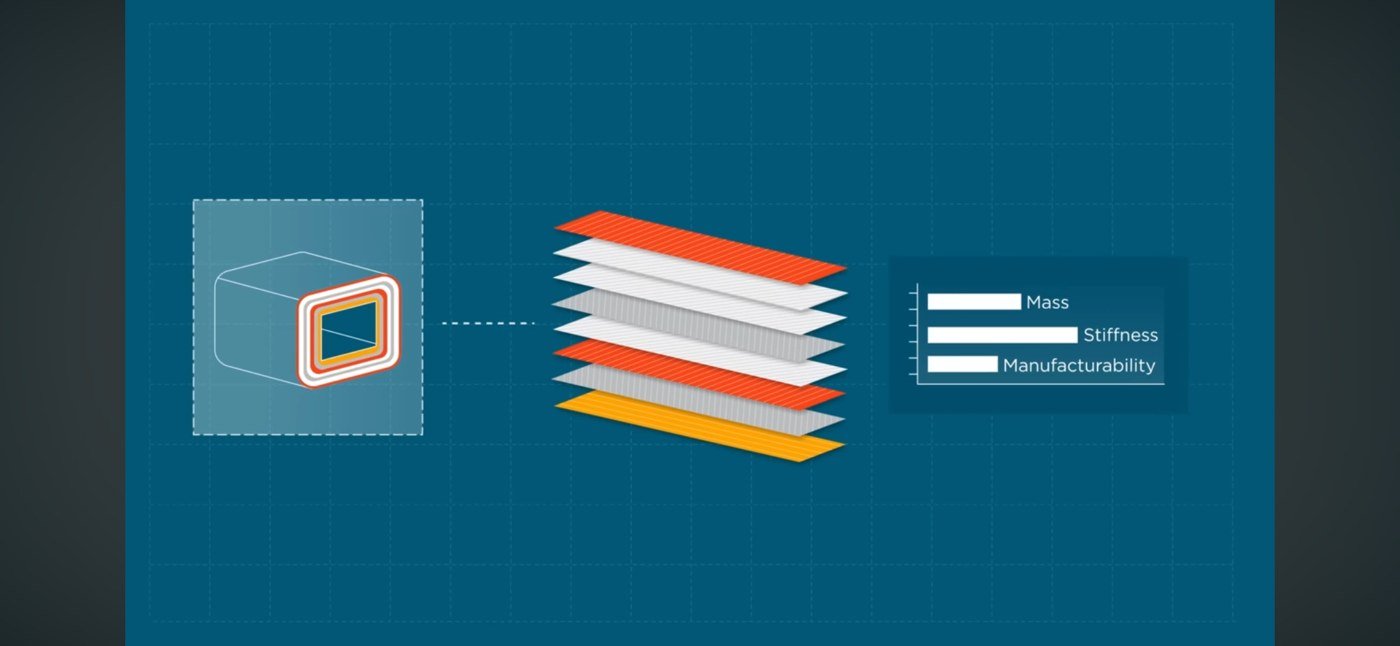
Every layup is a tradeoff, resolved computationally.
Mass, stiffness, and manufacturability pull in different directions. Sizing the stack against all three at once, rather than iterating between separate tools, is what makes the tradeoff tractable. The Virtua Composites platform allows efficient Design For Manufacturing (DfM) capabilities, through an innovative unified CAE and CAM kernel.
Our software can help you if: you need advanced manufacturing capabilities added to your current design or engineering workflow. Or if you can't justify an expensive generic CAE-CAM license (FEA or robot offline-programming/OLP software) for occasional or highly specific use.
Built for the realities of composite manufacturing.
Not a scaled-down commercial suite, and not a research script: a tool sized for the problem, built on foundations that have earned their track record.
Two software solutions, one same technology
Two frontend solutions, one for generating a robot program for real deposition, and another for sizing structures with accurate manufacturing constraints. But same core engine technology.
Cloud-based or On-Premises
The software platform is available either from the Cloud (ideal for academic usage or for starting), with no installation required and automatic software updates. Or fully installed locally (On-Prem), for full confidentiality of data.
Simulation built for engineers
Design and size parts while accounting for shopfloor constraints (robot reach, tow width, tooling geometry, cure limits) alongside structural requirements, not after the fact.
Standalone, or coupled
Run it on its own, or couple it directly with the CAD-CAE standards already in your workflow. No forced migration to a new platform.
Cheaper than commercial platforms
FREE license for academic and start-ups, for basic software features. Pay only for your own custom and confidential features (on-demand). We are a very reactive team.
20+ years in the field
Developed on the back of two decades of experience in automated composites manufacturing, robotics, and structural engineering.
Mold in. Robot program out.
Seven stages, each grounded in an established method rather than a heuristic.
Mold & tooling
Import STEP mold surfaces and solids, mesh and analyse them, and define the Edges-Of-Part (EEOP/MEOP) contours that bound the layup, with advanced rosette transfer capabilities.
Laminate design
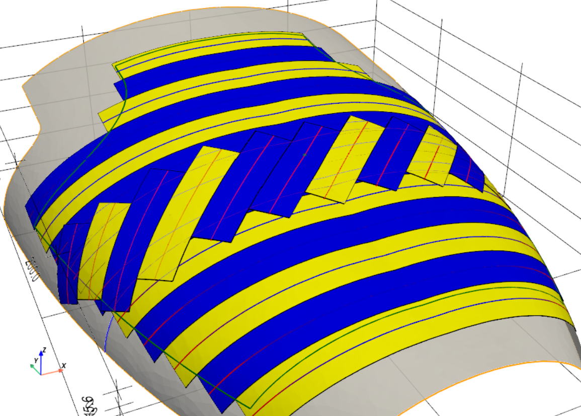
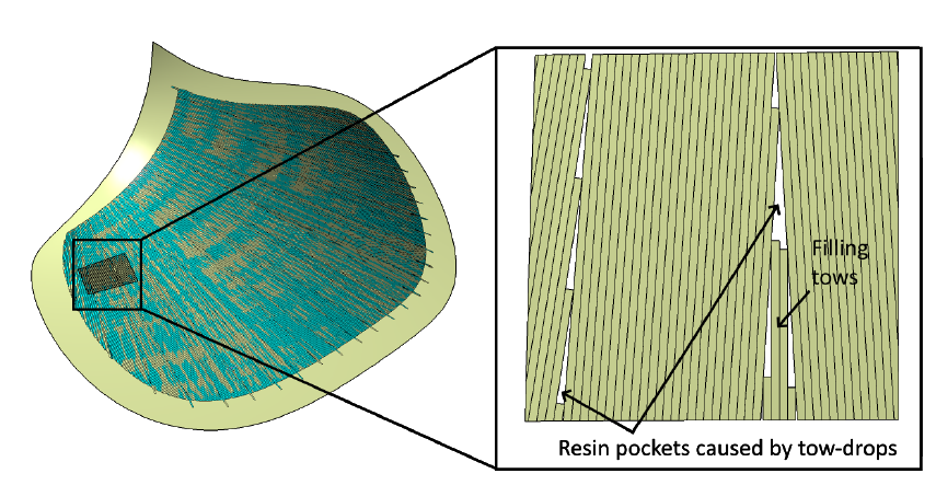
Build up plies (AFP) or winding layers (filament winding) with fiber angles, guide curves, tape/tow courses, and winding patterns, with tapes analysis (fiber deviation angle, steering curvature radius, gaps/laps).
Process planning
Compute deposition toolpaths from the laminate or winding design, with configurable speeds, cartesian planning with custom target points distribution, and layup direction strategies.
Kinematics & simulation
Import a robot cell (URDF), configure inverse kinematics, jog the robot, and run a full collision-checked simulation of the deposition sequence.
Program generation
Export the simulated toolpath as a robot program (ABB RAPID, KUKA, or generic NC) or through a user-defined post-processor (scripting API), ready to run on the real cell.
Finite element simulation
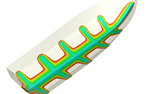
Transfer the manufacturing data (fiber directions, thicknesses, temperature) for accurate structural strength analysis, and send as-manufactured preform data for stamping or resin infusion process simulation.
Digital Twin
Connect to the physical asset (robotic workcell), for very accurate program cycle-time in simulation, or for getting measurements (temperature through IR camera, robot speed, metrology data) for validating the design intent. Strong knowledge of industrial virtual controllers (ex: Siemens VNCK / Sinumerik-One, ABB RobotStudio).
Built around the processes it programs.
Each composite process has different constraints. Virtua Composites CAE-CAM treats each as a first-class case, not a variant of one generic toolpath model.
Process selection
Identify the best manufacturing process for your engineering problem, weighing part geometry and material against AFP, ATL, filament winding, forming, RTM process, and curing before committing to a toolpath strategy.
Productivity rate estimation
High-accuracy deposition and cycle-time estimates from the actual toolpath and process parameters, so throughput numbers hold up once the part is on the machine.
Physics-based simulation
Built for manufacturing engineers, not simulation specialists: governing equations for mechanics and process physics, not empirical curve-fits, drive every result.
AI assistant
An assistant grounded in composites engineering and automated manufacturing, for questions on laminate design, process selection, and toolpath strategy as you work. You don't buy a software only, but a large experience and expertise as well.
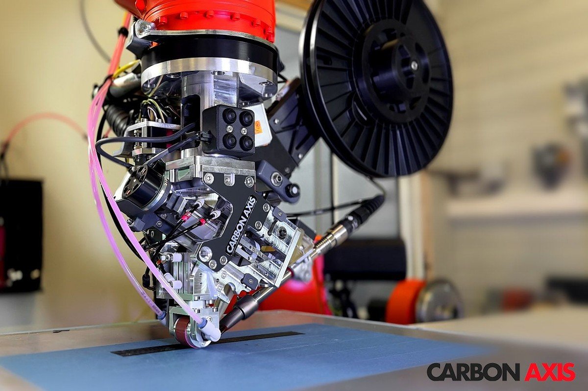
Built around how tow actually gets placed.
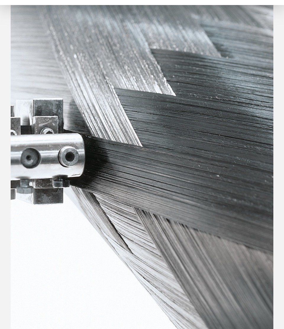
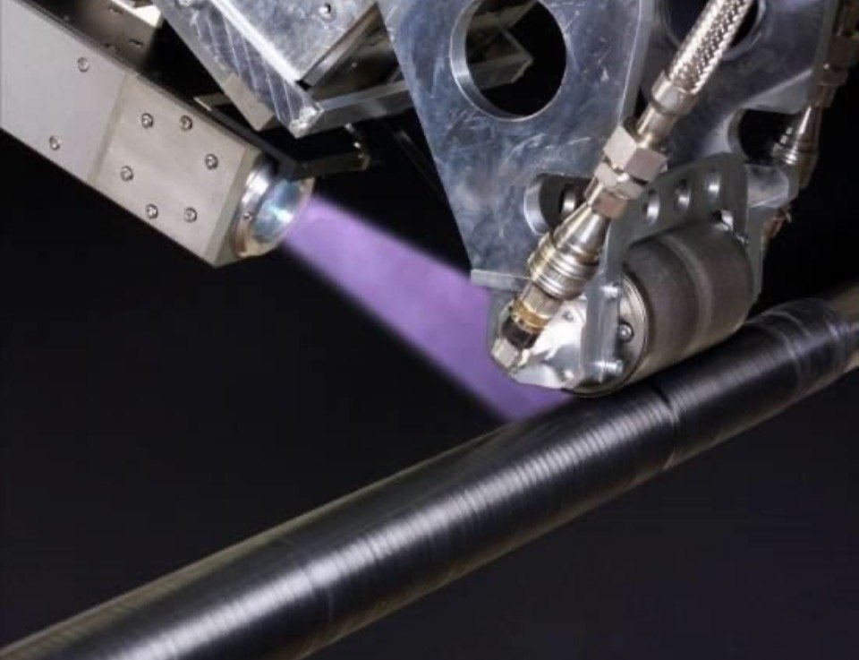
Toolpaths are only as good as the physical process they describe. These are the kinds of end effectors and feed systems the pipeline is built to represent.
Purpose-built vs. commercial platforms.
Commercial suites bundle every feature into one license. Virtua Composites CAE-CAM starts from fiber mechanics and gives you what the job needs.
Commercial CAM platforms
- Full-suite licensing, regardless of which features you use
- Closed-source core, hard to extend or audit
- Sizing and toolpath planning often live in separate tools
- Shopfloor constraints handled as a late-stage check, if at all
Virtua Composites CAE-CAM
- Not generic CAM-CAE platform, but composites engineering and manufacturing-oriented. Free or cheap for basic features. Pay for your specific needs only.
- Standalone, or coupled directly with your existing CAD-CAE stack
- Shopfloor constraints built into sizing and planning from the start
- Grounded in 20+ years of automated composites, robotics, and structural engineering experience
Engineering services for CAM programming.
Beyond the software, we support your team with composites manufacturing engineering, from feasibility to shopfloor-ready programs.
Design for manufacturing and feasibility studies
Early review of your part geometry, laminate and material against AFP, ATL, filament winding, forming, RTM process, and curing constraints, with clear recommendations before tooling is committed.
Productivity rate estimation
Deposition, winding, and cycle-time estimates built from simulated toolpaths, to support quotations and production planning.
Expert consulting
Hands-on support from engineers with 20+ years in automated composites, robotics, and structural analysis: process selection, programming strategy, troubleshooting.
Software training: basic and advanced
From first steps to advanced toolpath strategies, tailored to your team, parts, and machines.
Prefer a local install?
Virtua Composites CAE-CAM is also available as a desktop application, with installation binaries for Windows, macOS and Linux Ubuntu. Builds are provided on request and matched to your platform, so get in touch and we'll send you the current release.
Here are some of our contributions to the open-source community.
Our contributionsCommon questions
What manufacturing processes does Virtua Composites CAE-CAM support?
Automated fiber placement (AFP), automated tape laying (ATL), filament winding (geodesic, semi-geodesic, and helical patterns), forming, RTM process, and curing, including kinematic draping over developable and double-curved tooling.
Can it run alongside my existing CAD-CAE tools?
Yes. Virtua Composites CAE-CAM can be used standalone, or coupled directly with the CAD-CAE standards already in your workflow. There's no requirement to migrate your data or switch platforms. Notice that the software is able to import geometry in various formats (STEP, IGES, Rhino3D, Siemens NX, Solidworks, ACIS), and is also able to import NX/FiberSim XML composites engineering data.
Why is it more affordable than commercial CAM suites?
It's built on mature, robust, and massively-used open-source technologies rather than a closed, monolithic platform. That means the feature set and the cost match what you actually use, instead of paying for a bundled suite. Our strategy also consists at offering free or very low-cost basic software and do business for specific feature development and expertise.
What robots does it export to?
ABB RAPID is fully supported, alongside KUKA KRC and Siemens NC formats. Kinematics extend beyond the robot itself to external axes such as track rails and rotational positioners, so multi-axis cells export with the same fidelity as a standalone arm.
Why using open-source dependencies? Is it risky?
The opposite: it's a robustness choice. Building on proven open-source libraries means relying on components that are maintained and stress-tested by a large community, not by one vendor's roadmap. That gives a long-term maintained, thoroughly reviewed foundation, with bugs found and fixed faster than any single closed team could manage on its own. It's also why the platform stays lean: dependencies are chosen deliberately, not bundled by default.
I prefer developing my own software application (frontend). Can I use the CAE-CAM kernel through an API or SDK?
Yes, it is definitely possible. The software was built for this usage.
I have my own machine kinematics model, and I want to keep the IP and control the modeling myself. Is it possible?
Yes, it was designed that way. We support the existing universal XML format from ROS (URDF), which lets you freely build your own, or use any commercial CAD software to generate it. We support all kinds of kinematics (robotic cells with auxiliary devices, cartesian CNC machine-tools, hexapod mechanisms). We also provide documentation to help extend this file with custom attributes (process-specific). The post-processor can be specialized in a very similar way.
They trust us



Where to find us
Conferences and exhibitions where we're presenting our work.

SAMPE Europe 2026
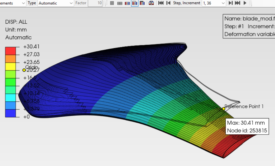
Paper: Manufacturing-Aware Structural Analysis of Composite Propeller Blades Using Open-Source platform.
Visit website →
JEC World Paris 2027
The leading international composites show. Details to follow.
Visit website →
Have a fiber placement or winding problem to plan?
Get in touch to talk through the geometry, the process, and what a toolpath and simulation pipeline for it could look like.
Get in touch